Our Location
304 North Cardinal St.
Dorchester Center, MA 02124

304 North Cardinal St.
Dorchester Center, MA 02124
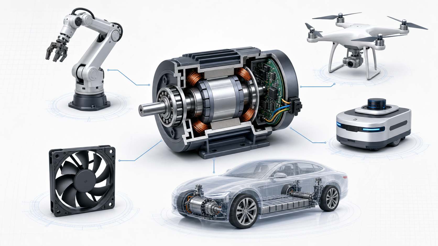
Brushless DC (BLDC) motors are widely used in modern industrial equipment, robotics, drones, electric vehicles, household appliances, and countless other applications. However, many beginners are often confused by the large number of technical terms, specifications, and design concepts associated with these motors.
This guide explains the fundamentals of BLDC motors, including their construction, operating principles, key components, important specifications, and common engineering terminology. By understanding these concepts, readers will gain a solid foundation for selecting, using, and maintaining brushless motors.
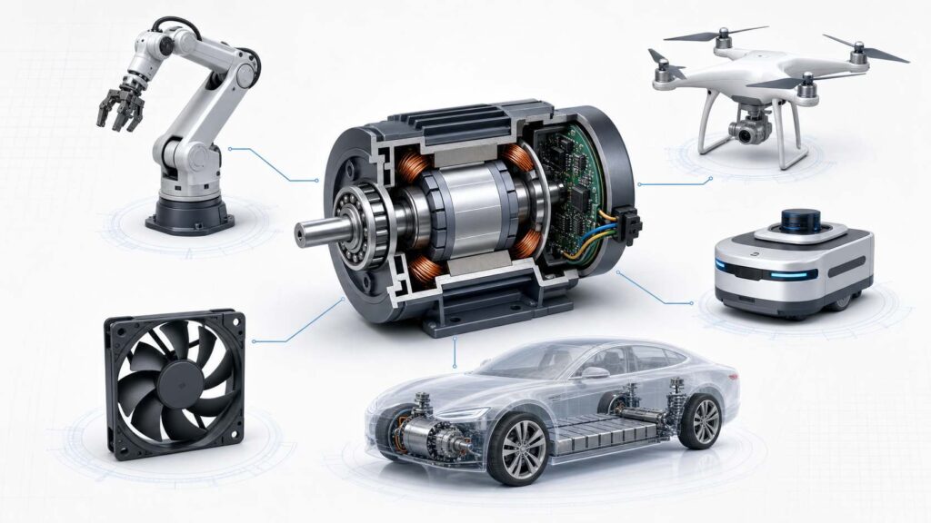
(Illustration: Various brushless DC motors used in industrial automation, drones, robots, cooling fans, and electric vehicles.)
Electric motors can be classified in many different ways. From the perspective of motor construction and commutation method, the most common types include:
Within the BLDC category, motors are commonly divided into inrunner motors and outrunner motors, depending on whether the rotor is located inside or outside the stator.
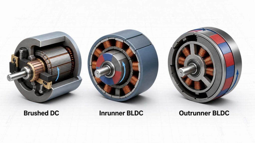
(Illustration: Comparison of a brushed DC motor, an inrunner BLDC motor, and an outrunner BLDC motor.)
Brushed DC motors are one of the oldest and most widely used motor technologies. They use carbon brushes and a mechanical commutator to switch the current flowing through the armature windings as the rotor rotates.
In a brushed motor:
Brushed motors offer several advantages:
However, because the brushes are in constant physical contact with the commutator, brushed motors also have several limitations:
Today, brushed DC motors are still widely used in cost-sensitive applications where extremely long service life or maximum efficiency is not required.
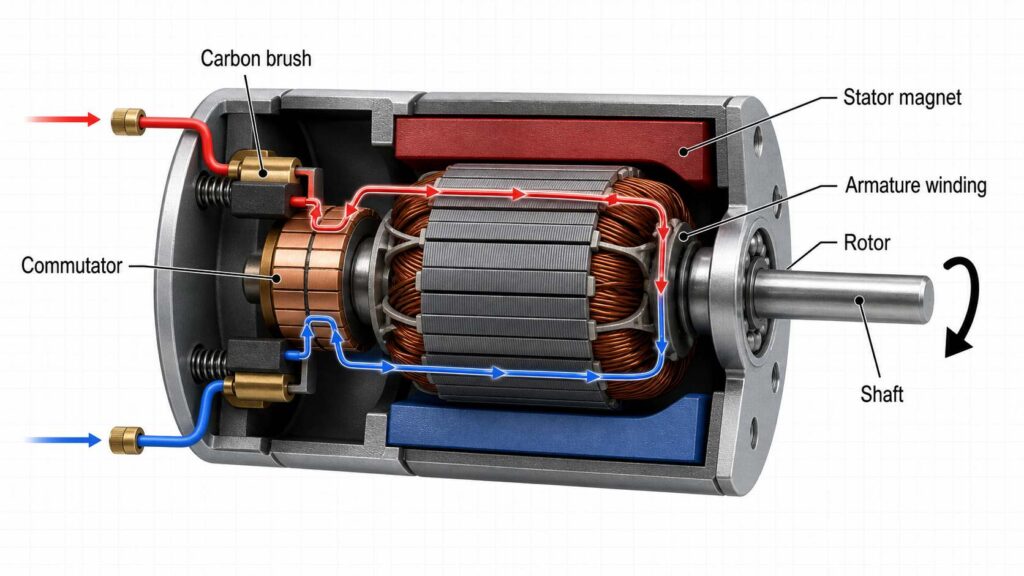
(Illustration: Cross-sectional diagram of a brushed DC motor showing the rotor, stator, carbon brushes, commutator, and current flow.)
Brushless DC (BLDC) motors eliminate the mechanical brushes and commutator found in traditional DC motors. Instead, current is switched electronically by an external motor controller or Electronic Speed Controller (ESC).
Unlike brushed motors:
Correction to the original article:
The original text implies that BLDC motors use Hall sensors for commutation. While Hall-effect sensors are common, many modern BLDC motors—especially those used in drones, fans, and pumps—operate without Hall sensors using sensorless control, which estimates rotor position from the motor’s back electromotive force (back EMF).
Compared with brushed motors, BLDC motors provide significant advantages:
The primary disadvantages are:
Despite these drawbacks, BLDC motors have become the preferred solution for many modern applications because of their overall performance and reliability.
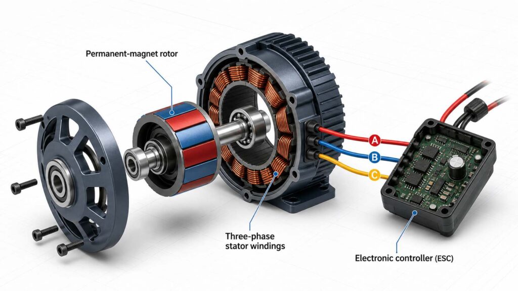
(Illustration: Internal structure of a brushless DC motor highlighting the permanent-magnet rotor, stator windings, and electronic controller.)
Unlike a brushed DC motor, a BLDC motor cannot operate simply by connecting it directly to a DC power supply.
A complete BLDC drive system normally consists of:
The ESC continuously energizes different stator windings in the correct sequence according to the rotor position, creating a rotating magnetic field that drives the rotor.
Without this electronic commutation process, a BLDC motor cannot produce continuous rotation.
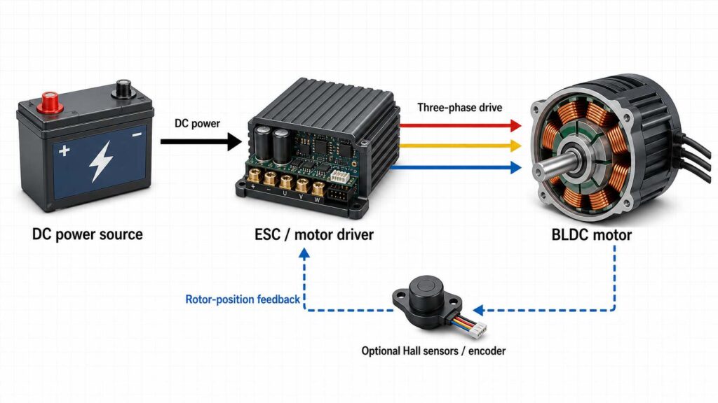
(Illustration: Block diagram showing a battery, ESC, BLDC motor, and optional Hall sensor feedback.)
Every electric motor consists of two primary components:
In a typical BLDC motor:
The stator consists of laminated electrical steel cores and insulated copper windings. When energized by the controller, these windings generate a rotating magnetic field.
The rotor contains permanent magnets that rotate in response to the stator’s magnetic field. Modern BLDC motors typically use high-performance neodymium iron boron (NdFeB) magnets because of their high magnetic energy density.
The interaction between the rotating magnetic field and the permanent magnets produces the torque that drives the motor.
The number of magnetic pole pairs also influences motor characteristics such as speed, torque, and electrical frequency, which will be discussed in later sections.
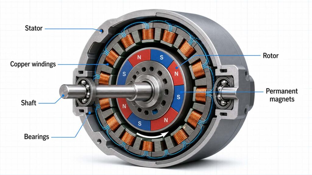
(Illustration: Cross-sectional view of a BLDC motor labeling the stator, rotor, windings, permanent magnets, shaft, and bearings.)