Our Location
304 North Cardinal St.
Dorchester Center, MA 02124

304 North Cardinal St.
Dorchester Center, MA 02124
Understanding how a Brushless DC (BLDC) motor works is essential for understanding why it delivers higher efficiency, longer service life, and better controllability than a traditional brushed DC motor.
Unlike a brushed motor, which relies on mechanical brushes and a commutator to reverse the current flowing through the rotor windings, a BLDC motor performs this switching electronically. An electronic controller energizes the stator windings in a specific sequence, creating a rotating magnetic field that continuously pulls the rotor forward.
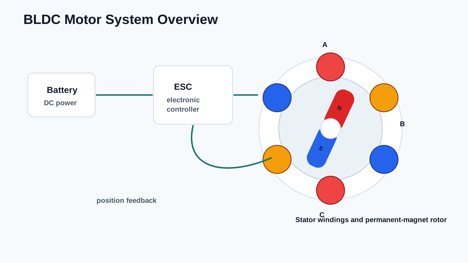
(Illustration: Overview of a BLDC motor system showing the battery, electronic speed controller (ESC), stator windings, and permanent-magnet rotor.)
A typical BLDC drive system consists of four basic elements:
The controller continuously determines the rotor position and energizes the appropriate stator windings to maintain smooth rotation.
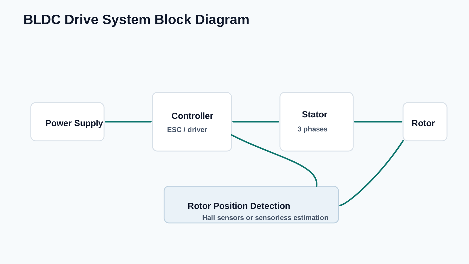
(Illustration: Block diagram showing the relationship between the power supply, controller, rotor position detection, stator, and rotor.)
To generate continuous torque, the controller must know the approximate position of the rotor at all times. There are two common methods of obtaining this information.
Many industrial BLDC motors include Hall-effect sensors mounted inside the motor. These sensors detect changes in the magnetic field produced by the permanent magnets and provide position signals to the controller.
Hall sensors offer several advantages:
Hall-sensor-based motors are commonly used in electric bicycles, industrial equipment, robotics, and automotive systems.
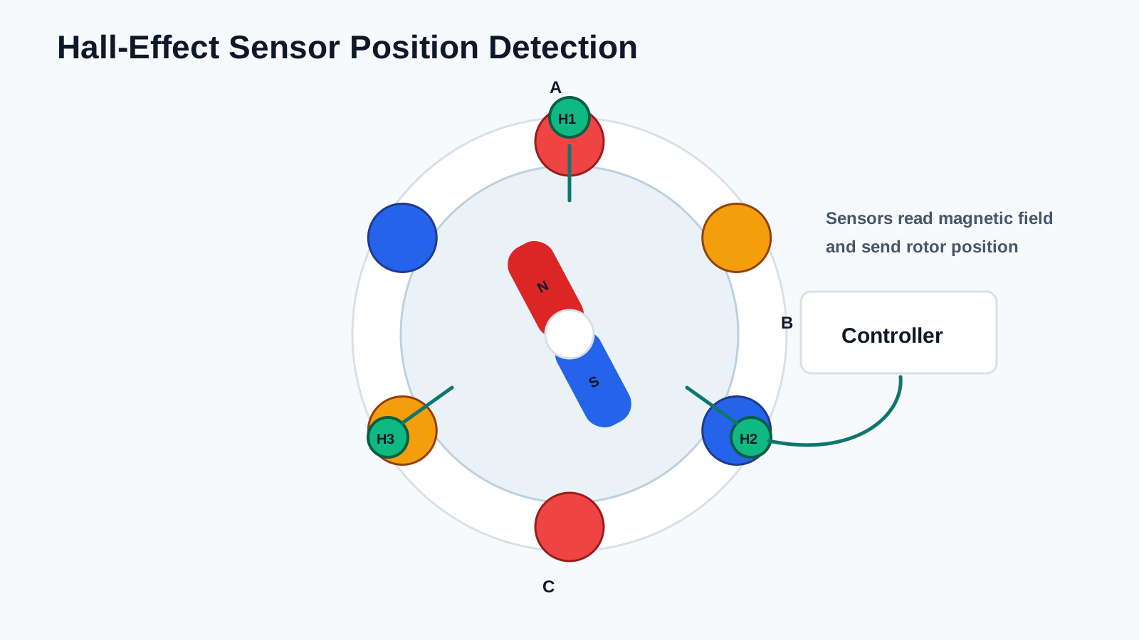
(Illustration: Three Hall-effect sensors mounted around the stator, detecting the rotor’s permanent magnets.)
Many modern BLDC motors operate without Hall sensors.
Instead, the controller estimates the rotor position by monitoring the back electromotive force (Back EMF) generated in the unpowered phase windings.
Sensorless control offers several benefits:
However, because back EMF is very small at low speeds, sensorless motors generally require more sophisticated starting algorithms than Hall-sensor motors.
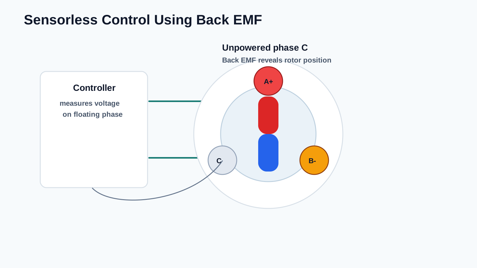
(Illustration: Simplified diagram showing how a controller estimates rotor position using back EMF from the unpowered phase.)
Note:
The original article mainly describes Hall-sensor-based systems. Modern BLDC motors are available in both Hall-sensor and sensorless versions, and both are widely used depending on the application.
The defining characteristic of a BLDC motor is electronic commutation.
Instead of using brushes and a mechanical commutator, the controller energizes different stator windings electronically.
As the rotor rotates, the controller continuously switches current between the three motor phases, causing the magnetic field inside the stator to rotate.
The rotor’s permanent magnets naturally follow this rotating magnetic field, producing continuous mechanical rotation.
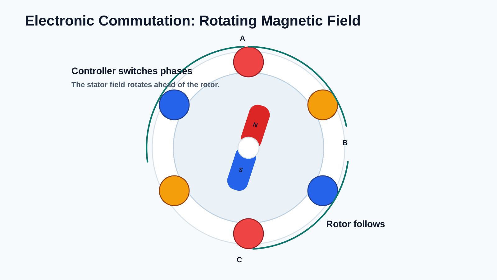
(Illustration: Rotating magnetic field inside the stator pulling the permanent-magnet rotor through successive positions.)
The operating sequence of a BLDC motor can be summarized as follows:
This process repeats thousands of times every second while the motor is running.
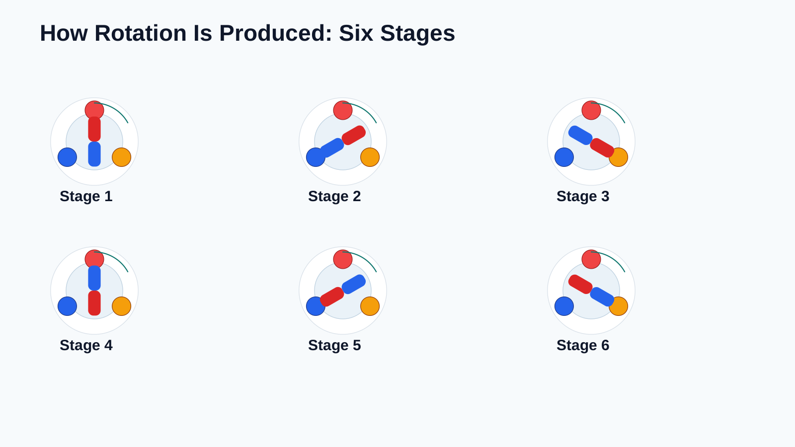
(Illustration: Sequential diagram showing six stages of rotor movement as the magnetic field rotates.)
Most BLDC motors use a three-phase stator consisting of three independent winding groups, commonly identified as:
These windings are typically connected in either:
The star connection is the most common configuration for many industrial and consumer BLDC motors because it provides good efficiency and smooth operation.
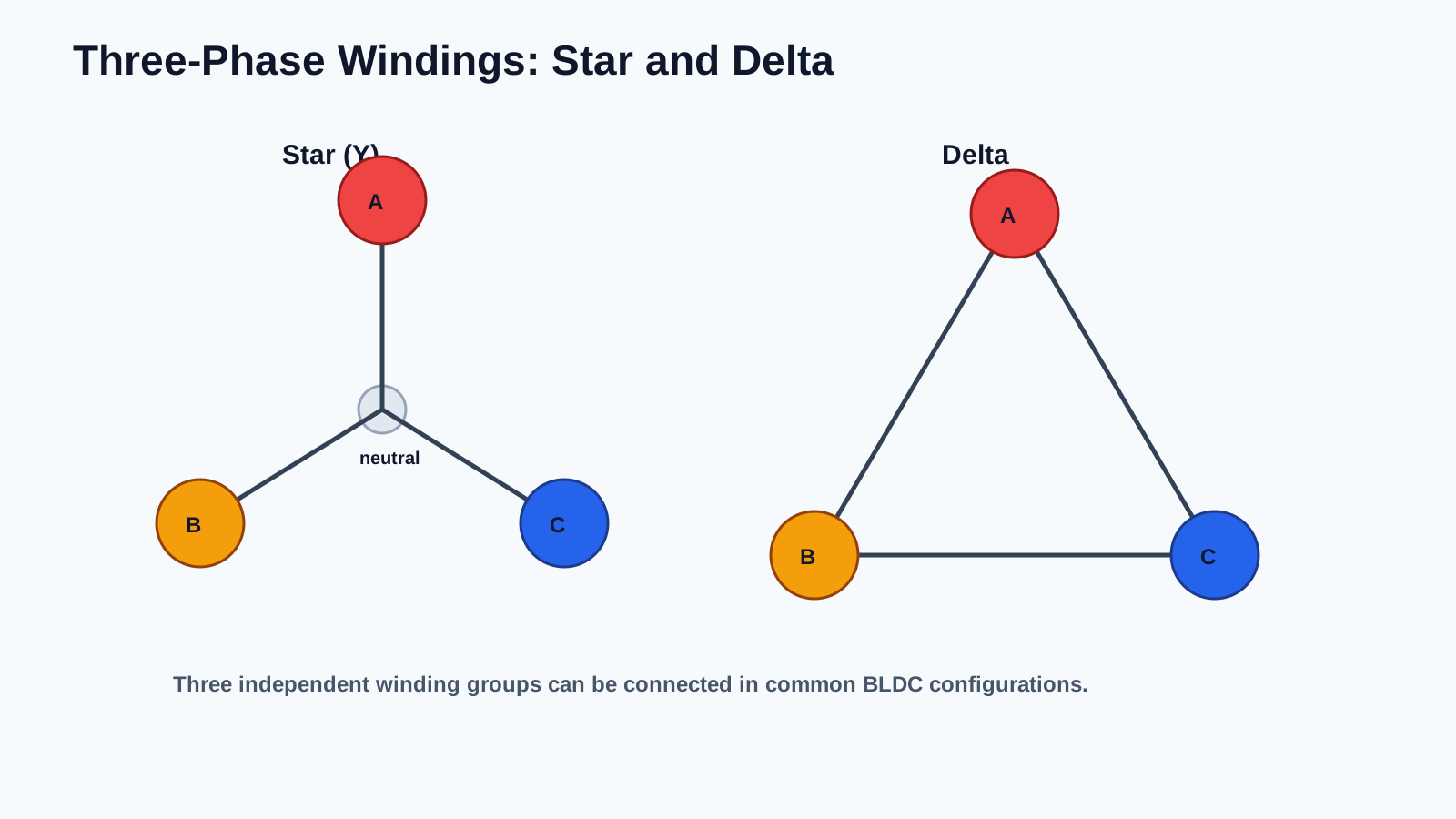
(Illustration: Three-phase stator winding connected in both star (Y) and delta (Δ) configurations.)
One of the most common control methods for BLDC motors is six-step commutation, also known as trapezoidal commutation.
During each electrical cycle, two phases are energized while the third phase remains unpowered.
The controller energizes the phases in the following sequence:
After the sixth step, the sequence repeats continuously.
Each commutation step rotates the stator’s magnetic field, causing the rotor to advance toward its next position.
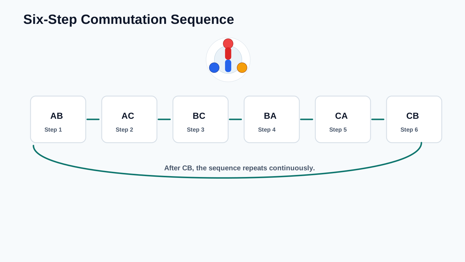
(Illustration: Six-step commutation sequence showing the AB → AC → BC → BA → CA → CB switching order and the corresponding rotor positions.)
Engineering Note:
The original article explains each commutation state individually with separate diagrams. For clarity and readability, the sequence is summarized here because the operating principle remains the same regardless of the motor’s physical size.
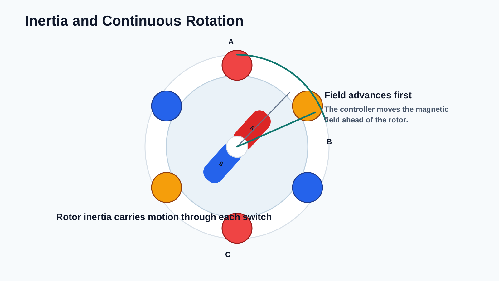
When the controller switches to the next commutation state, the rotor does not stop at each magnetic position.
Instead, its rotational inertia allows it to continue moving while the controller advances the magnetic field ahead of the rotor.
By continuously moving the magnetic field forward, the controller maintains uninterrupted rotation.
This principle is fundamental to all electronically commutated motors.
(Illustration: Diagram showing the magnetic field advancing ahead of the rotor to maintain continuous rotation.)
During six-step commutation, electrical current flows through only two phases at a time.
One phase is connected to the positive supply.
One phase is connected to the negative supply.
The remaining phase is temporarily left floating.
The floating phase can also be monitored by the controller to estimate the rotor position in sensorless systems.
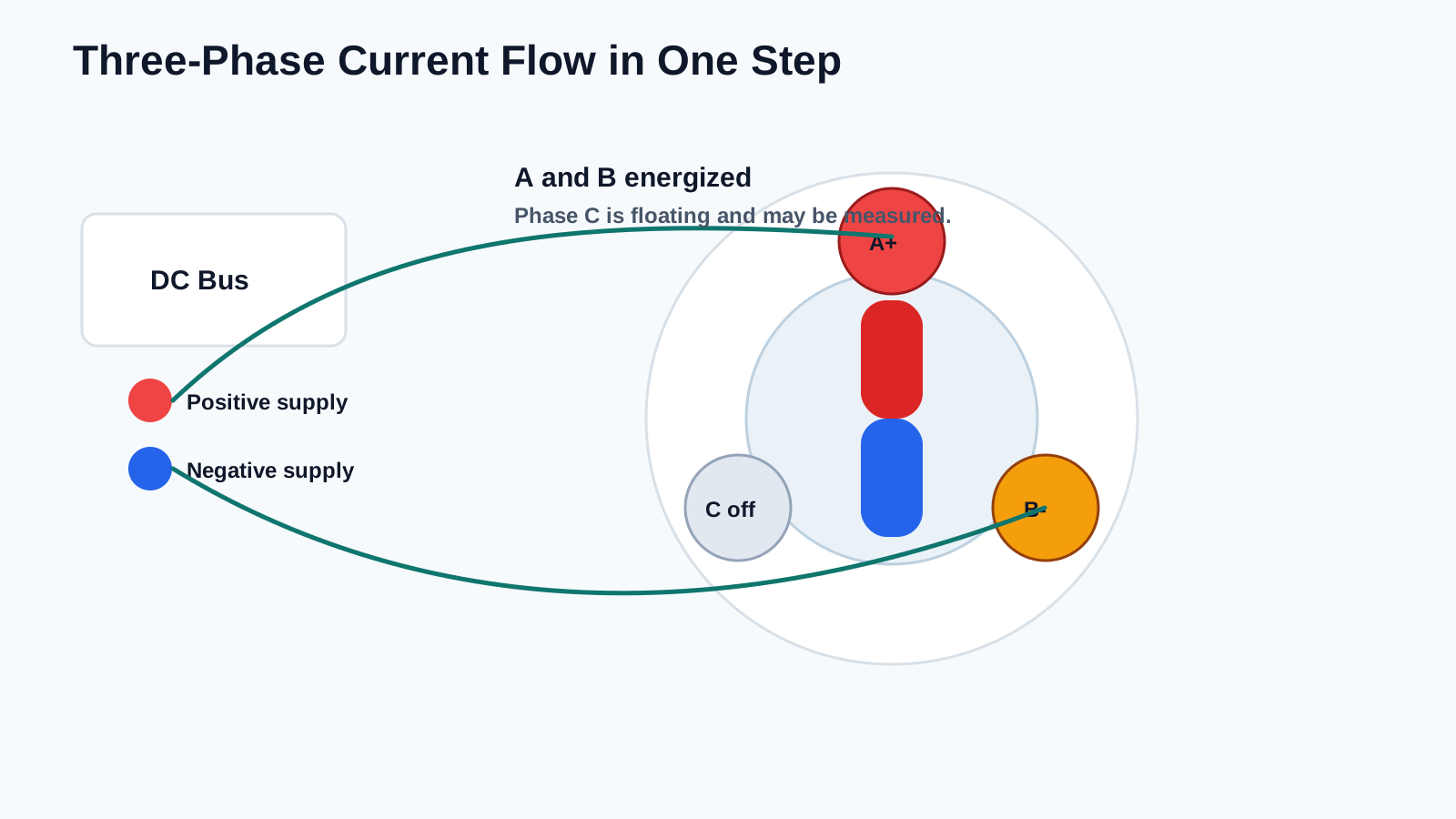
(Illustration: Three-phase current flow during one commutation step, highlighting the energized phases and the floating phase.)