Our Location
304 North Cardinal St.
Dorchester Center, MA 02124

304 North Cardinal St.
Dorchester Center, MA 02124
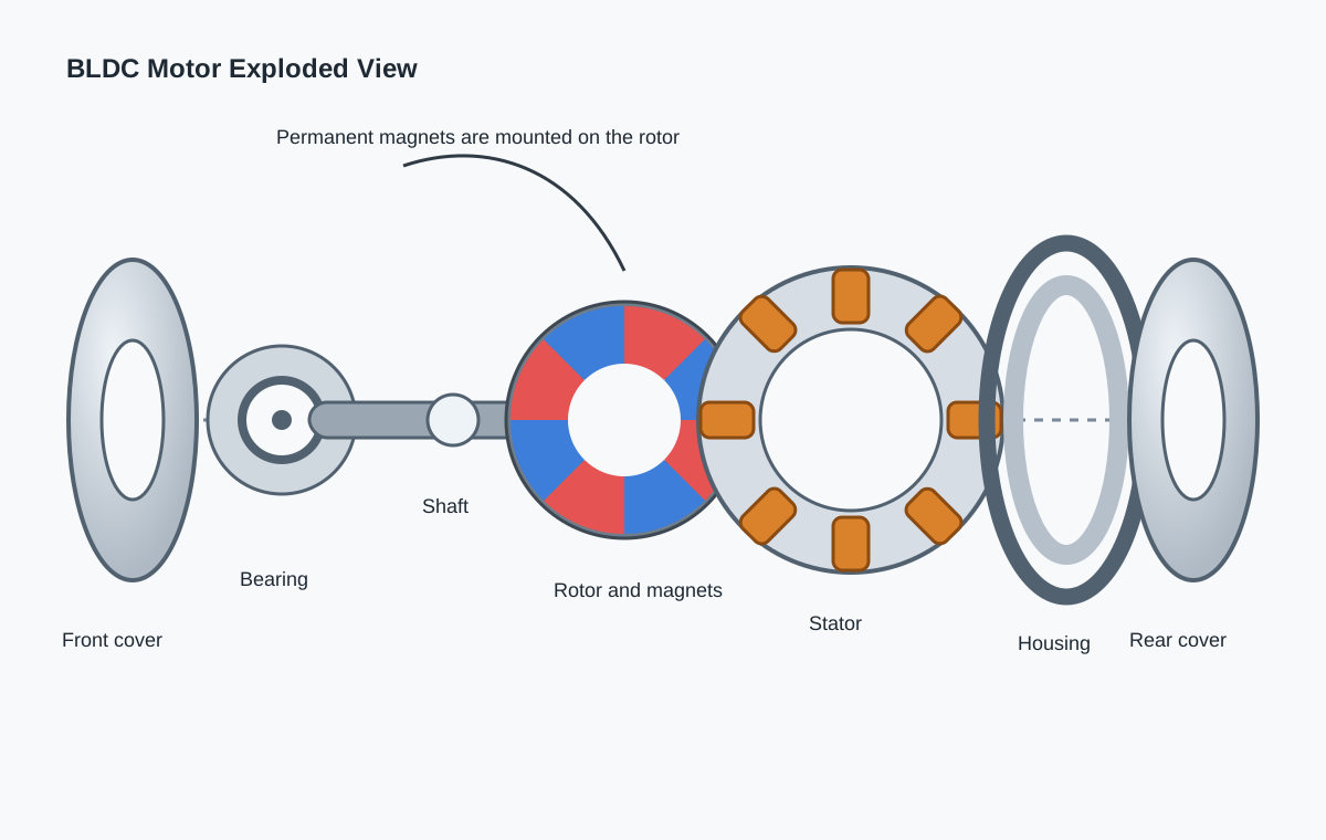
Although brushless DC motors are available in many sizes and configurations, most share the same basic construction. Understanding the function of each component helps explain how a BLDC motor delivers high efficiency, reliable operation, and long service life.
(Illustration: Exploded view of a brushless DC motor showing the front cover, rear cover, housing, stator, rotor, shaft, bearings, and permanent magnets.)
A typical brushless DC motor consists of the following major components:
Each component performs a specific function within the motor, and together they determine the motor’s overall performance.
The front cover, rear cover, and motor housing provide the mechanical structure that supports and protects the internal components.
Their primary functions include:
The housing design differs between inrunner and outrunner motors.
In an inrunner motor, the outer housing remains stationary and mainly serves as a structural component. The rotor, mounted on the shaft, rotates inside the stator.
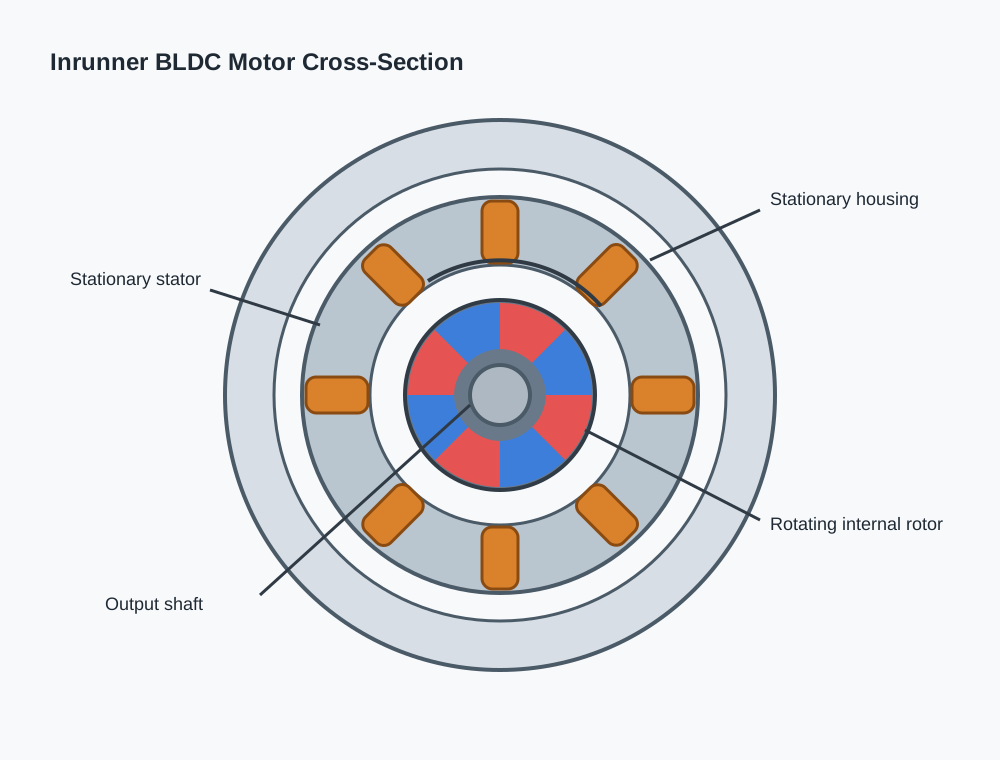
(Illustration: Cross-sectional view of an inrunner BLDC motor showing the stationary housing and rotating internal rotor.)
In an outrunner motor, the outer housing forms part of the rotating assembly. Permanent magnets are attached to the inside of the rotating outer shell, making the housing an essential part of the magnetic circuit as well as the rotor itself.
Because the housing carries magnetic flux, it is typically manufactured from ferromagnetic steel rather than aluminum or other non-magnetic materials.
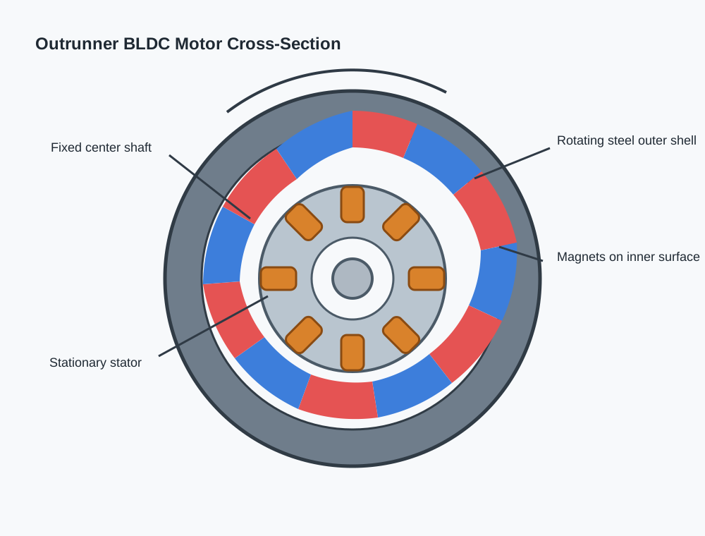
(Illustration: Cross-sectional view of an outrunner BLDC motor showing the rotating outer shell with permanent magnets attached to its inner surface.)
Permanent magnets are mounted on the rotor and are one of the most important components of a BLDC motor.
Their magnetic field interacts with the rotating magnetic field produced by the stator windings to generate torque.
The performance of a BLDC motor is closely related to the characteristics of its magnets, including:
Most modern BLDC motors use Neodymium Iron Boron (NdFeB) magnets because they provide significantly higher magnetic energy than traditional ferrite magnets while maintaining a compact size.
Different magnet grades are selected according to the application’s temperature requirements, cost targets, and performance goals.
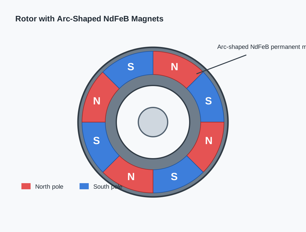
(Illustration: Rotor fitted with arc-shaped NdFeB permanent magnets, with magnetic poles labeled N and S.)
The stator core is constructed from thin laminated electrical steel sheets rather than a single solid piece of steel.
These laminations serve two primary purposes:
Without laminated steel, substantial energy would be lost as heat, reducing motor efficiency.
Most BLDC motors use slotted stators, where copper windings are placed inside precision-machined slots. Slotless designs also exist for specialized applications requiring exceptionally smooth rotation or very low cogging torque, but they are less common.

(Illustration: Close-up of laminated stator core with copper windings installed inside the stator slots.)
The motor shaft transmits the mechanical output of the motor to the driven equipment.
During operation, the shaft must withstand:
To ensure durability and dimensional stability, shafts are typically manufactured from hardened alloy steel or stainless steel, depending on the operating environment.
The shaft must also maintain precise concentricity with the rotor to minimize vibration and ensure smooth operation.
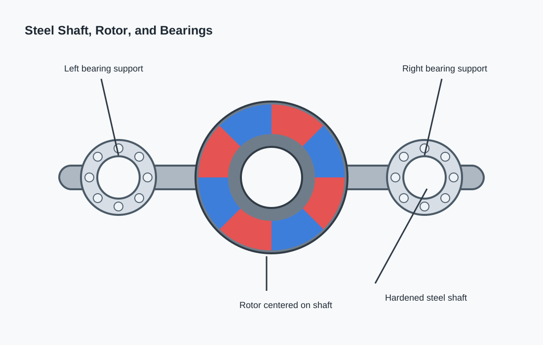
(Illustration: Steel motor shaft installed through the center of the rotor and supported by two bearings.)
Bearings support the rotating shaft and allow the rotor to rotate smoothly with minimal friction.
Bearing quality has a direct influence on:
The most common bearing types include:
Sleeve bearings have a simple structure and low manufacturing cost. They are suitable for light-duty, low-speed applications but generally have a shorter service life than rolling-element bearings.
Deep groove ball bearings are the most widely used bearings in BLDC motors because they provide:
Depending on the application, some motors may also use:
These specialized bearings are selected when higher speed, heavier loads, or extreme operating environments are involved.
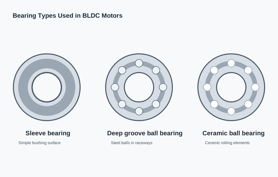
(Illustration: Comparison of a sleeve bearing, a deep groove ball bearing, and a ceramic ball bearing.)
A BLDC motor operates through the interaction between two key assemblies:
The permanent magnets on the rotor continuously align themselves with the magnetic field produced by the energized stator windings. As the electronic controller switches current between the windings, the magnetic field rotates, causing the rotor to rotate continuously.
Unlike a brushed DC motor, there is no physical electrical contact between the rotor and the power supply. This eliminates brush wear, reduces maintenance, and allows for quieter and more efficient operation.
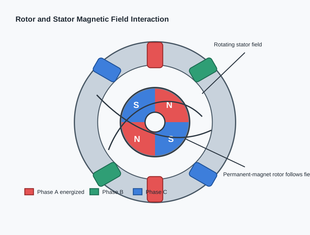
(Illustration: Simplified diagram showing the interaction between the stator’s rotating magnetic field and the permanent-magnet rotor.)