Our Location
304 North Cardinal St.
Dorchester Center, MA 02124

304 North Cardinal St.
Dorchester Center, MA 02124
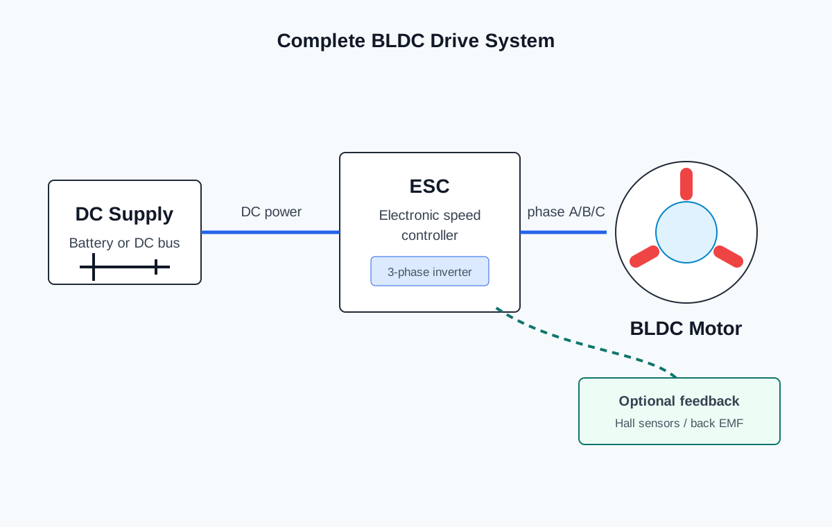
A brushless DC motor cannot operate independently. Unlike a brushed DC motor, which can rotate when connected directly to a DC power supply, a BLDC motor requires an electronic controller to energize the stator windings in the correct sequence.
The controller is therefore an essential part of every BLDC drive system. Its performance directly affects motor efficiency, smoothness, torque output, noise level, and overall reliability.
(Illustration: Complete BLDC drive system including a DC power supply, electronic speed controller (ESC), BLDC motor, and optional feedback sensors.)
In a brushed motor, the commutator and carbon brushes automatically reverse the current flowing through the rotor windings.
A BLDC motor has no brushes or commutator. Therefore, another method is required to continuously change the direction of the magnetic field.
This task is performed by the Electronic Speed Controller (ESC) or motor driver.
The controller continuously:
Without electronic commutation, the motor cannot produce continuous rotation.
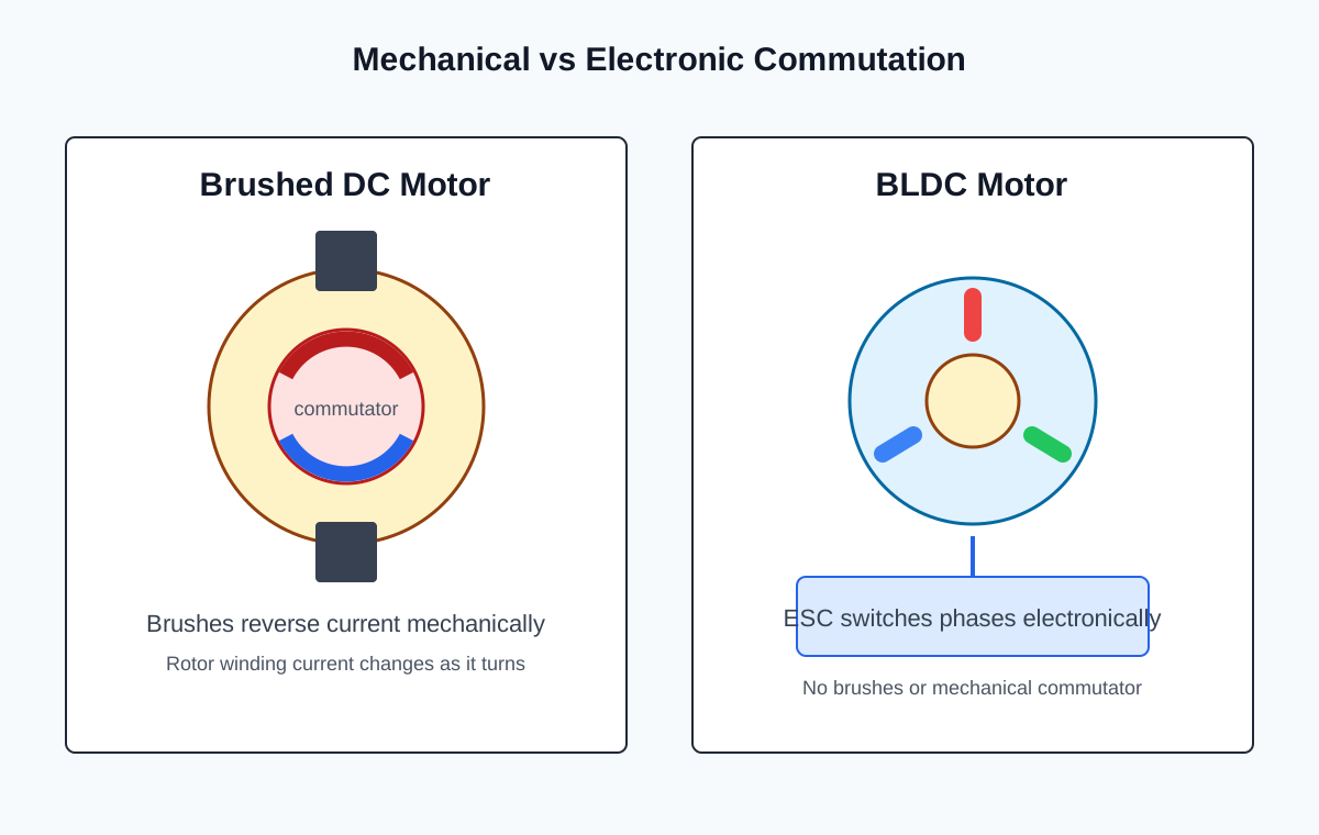
(Illustration: Comparison between mechanical commutation in a brushed motor and electronic commutation in a BLDC motor.)
The Electronic Speed Controller (ESC) is the electronic circuit responsible for driving the motor.
Its primary functions include:
Modern ESCs usually consist of:
The controller continuously processes feedback information and adjusts the switching sequence in real time.
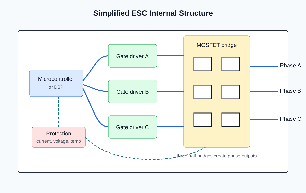
(Illustration: Simplified internal structure of an ESC showing the microcontroller, gate drivers, MOSFET bridge, and motor output terminals.)
One of the most common methods of controlling BLDC motor speed is Pulse Width Modulation (PWM).
Rather than continuously varying the supply voltage, the controller rapidly switches the voltage on and off at a high frequency.
The average voltage supplied to the motor depends on the duty cycle of the PWM signal.
For example:
Because the switching frequency is much higher than the motor’s mechanical response, the motor operates smoothly while maintaining high efficiency.
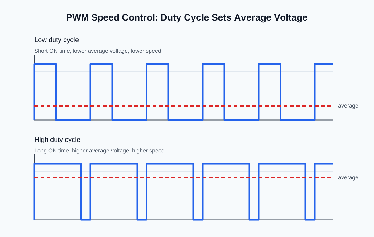
(Illustration: PWM waveforms showing different duty cycles and the corresponding average output voltage.)
Changing the rotation direction of a BLDC motor is relatively straightforward.
The controller simply changes the commutation sequence.
For example:
Forward rotation:
AB → AC → BC → BA → CA → CB
Reverse rotation:
BA → BC → AC → AB → CB → CA
Reversing the switching sequence causes the rotating magnetic field to rotate in the opposite direction, and the rotor follows accordingly.
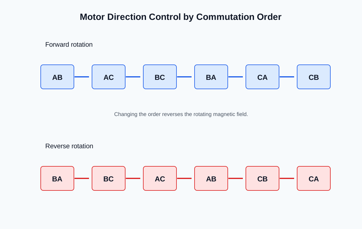
(Illustration: Diagram comparing forward and reverse commutation sequences.)
Starting a BLDC motor is more complex than maintaining its rotation.
For motors equipped with Hall-effect sensors, the controller immediately knows the rotor position and can energize the correct windings.
This provides:
Sensorless motors cannot detect back EMF when the rotor is stationary because no back EMF is generated at zero speed.
Therefore, the controller must first perform an open-loop starting sequence to begin rotor movement.
Once sufficient speed has been reached, measurable back EMF becomes available, allowing the controller to switch to closed-loop operation.
This transition is completely automatic in modern controllers.
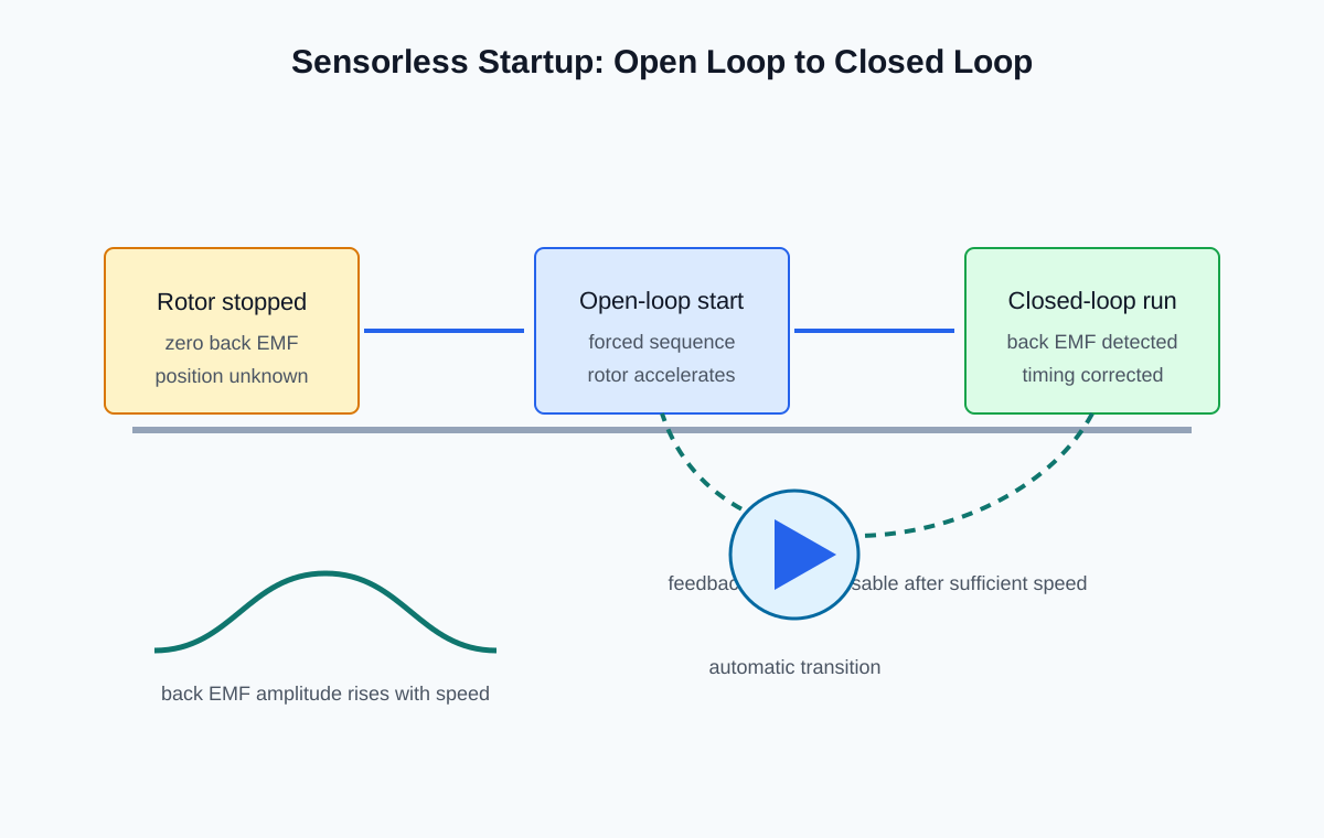
(Illustration: Sequence showing open-loop startup followed by closed-loop sensorless operation using back EMF feedback.)
As discussed previously, six-step commutation is one of the most widely used BLDC control methods.
Its main advantages include:
However, because current changes occur in discrete steps, six-step control may produce:
These characteristics are acceptable for many applications, including:
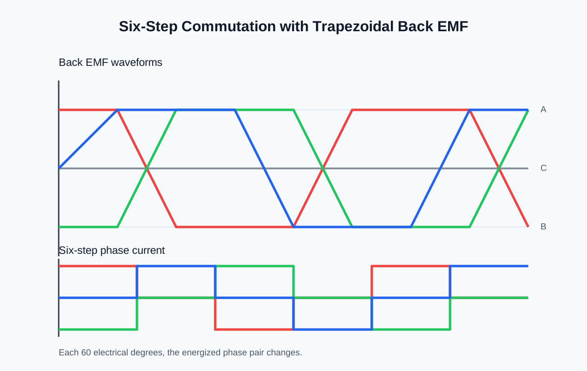
(Illustration: Trapezoidal back EMF waveform with six-step current commutation.)
As BLDC technology has advanced, many high-performance applications have adopted Field-Oriented Control (FOC).
Unlike six-step commutation, FOC continuously regulates the motor current using mathematical transformations, producing nearly sinusoidal current waveforms.
Compared with six-step control, FOC provides:
FOC is widely used in:
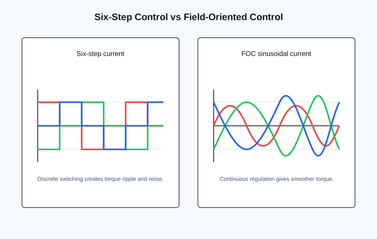
(Illustration: Comparison between six-step current waveforms and smooth sinusoidal current waveforms produced by FOC.)
Technical Note:
The original article focuses primarily on traditional six-step commutation. Because FOC has become the dominant control method in many modern BLDC applications, it is included here to provide readers with a more complete and up-to-date understanding of current motor control technologies.
Modern motor controllers typically include multiple protection features to improve system reliability.
Common protection functions include:
These functions help prevent damage to both the motor and the controller under abnormal operating conditions.
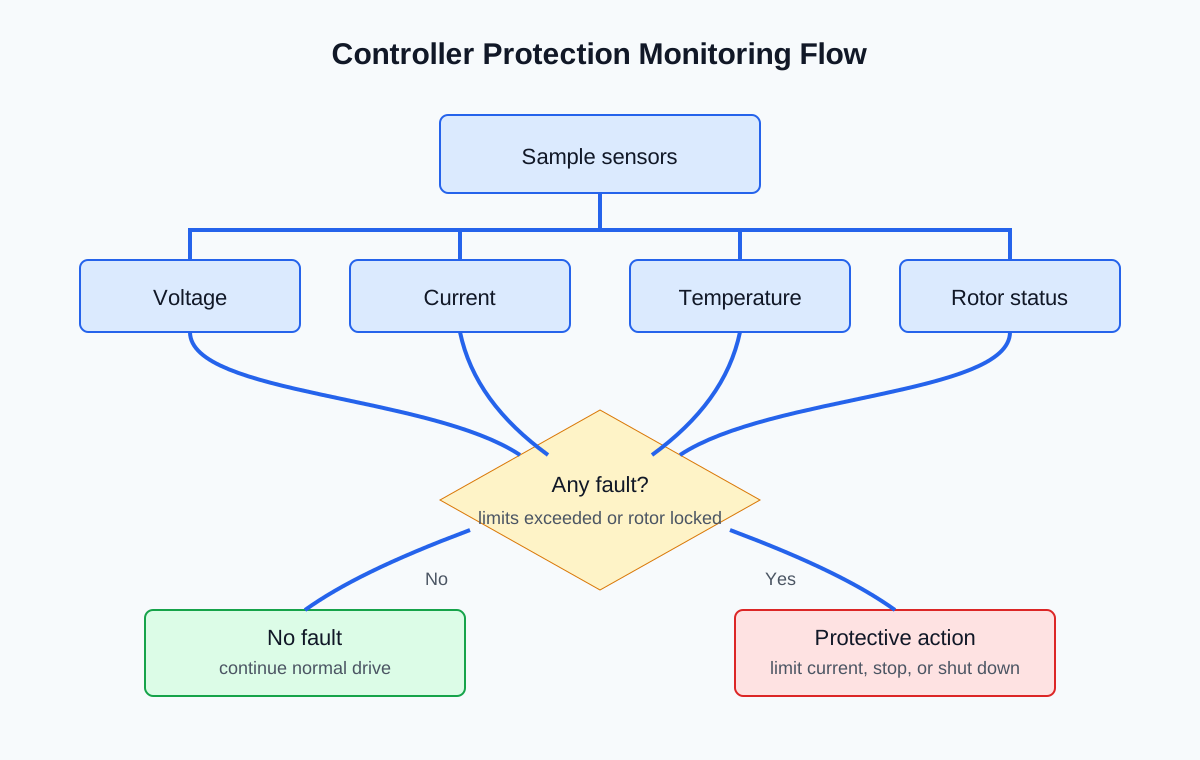
(Illustration: Flowchart showing the controller monitoring voltage, current, temperature, and rotor status while applying protective actions.)