Our Location
304 North Cardinal St.
Dorchester Center, MA 02124

304 North Cardinal St.
Dorchester Center, MA 02124
In the previous section, we explained how a BLDC motor generates continuous rotation through electronic commutation. Another important aspect of BLDC motor operation is the relationship between rotor configuration, magnetic pole design, and motor performance.
Many beginners assume that all brushless motors share the same internal construction. In reality, BLDC motors are available in different rotor configurations and pole arrangements, each designed to meet specific requirements for speed, torque, efficiency, size, and dynamic response.
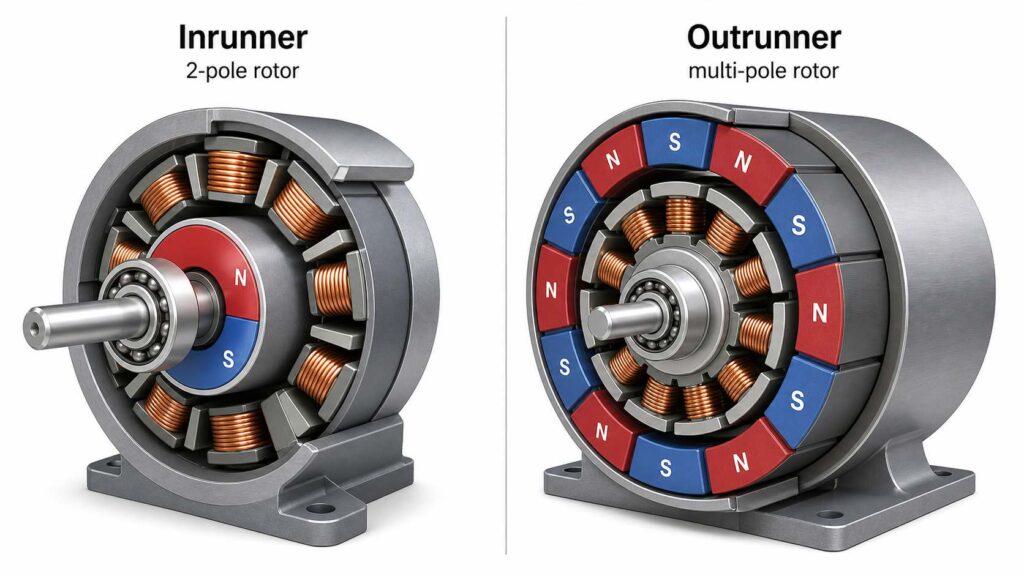
(Illustration: Comparison of several BLDC rotor configurations, including a two-pole inrunner rotor and a multi-pole outrunner rotor.)
BLDC motors are generally divided into two structural types according to the position of the rotor.
An inrunner motor places the rotor inside the stator. The stator windings surround the rotor, while the motor housing remains stationary.
Characteristics include:
Typical applications include:
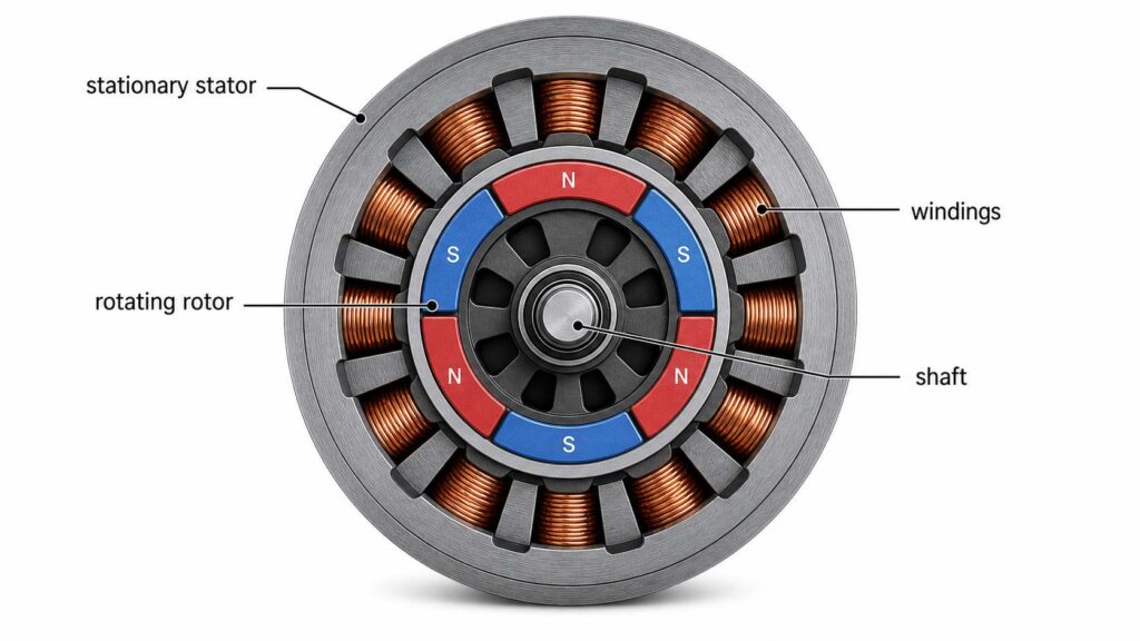
(Illustration: Cross-sectional view of an inrunner BLDC motor showing the internal rotating rotor and stationary outer stator.)
In an outrunner motor, the stator is fixed at the center, while the outer rotor rotates around it.
Permanent magnets are attached to the inner surface of the rotating outer shell.
Compared with inrunner motors, outrunner motors generally provide:
Because of their naturally high torque, outrunner motors are widely used in applications that require direct drive without significant gear reduction.
Typical applications include:
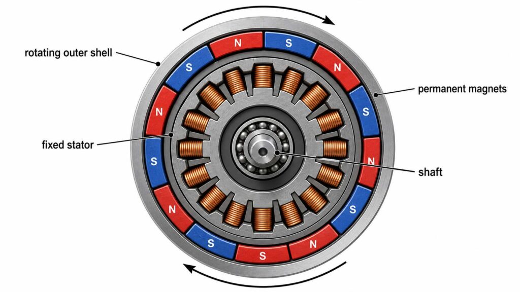
(Illustration: Cross-sectional view of an outrunner BLDC motor showing the rotating outer shell with internal permanent magnets.)
The permanent magnets mounted on the rotor form alternating north (N) and south (S) magnetic poles.
These magnetic poles interact with the rotating magnetic field generated by the stator windings to produce torque.
For stable operation, the poles are always arranged in alternating order:
N → S → N → S → N → S
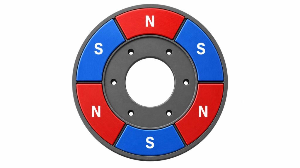
(Illustration: Rotor with alternating north and south magnetic poles evenly distributed around the circumference.)
Instead of referring only to the total number of poles, engineers often describe a motor by its pole pairs.
One north pole together with one adjacent south pole forms one pole pair.
Examples:
| Total Poles | Pole Pairs |
|---|---|
| 2 | 1 |
| 4 | 2 |
| 6 | 3 |
| 8 | 4 |
| 10 | 5 |
| 14 | 7 |
Pole pairs are an important parameter because they directly influence the electrical frequency and speed relationship of the motor.
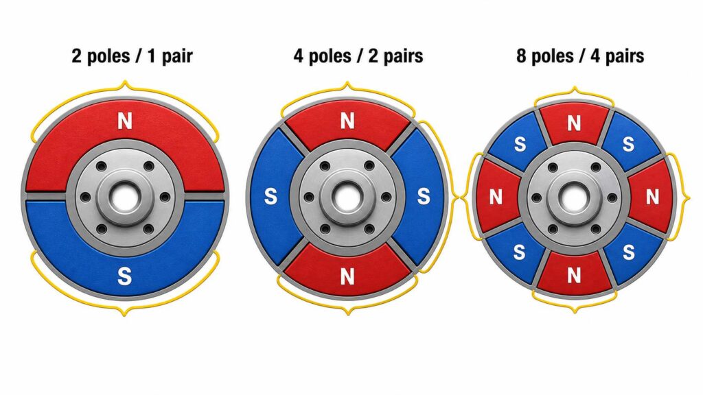
(Illustration: Rotor showing examples of 2-pole, 4-pole, and 8-pole designs with each pole pair highlighted.)
The original article explains that increasing the number of magnetic poles changes the motor’s operating characteristics. This principle remains correct, although it can be summarized more clearly.
Generally speaking:
For this reason:
The optimal pole count depends on the application’s requirements rather than one design being universally better than another.
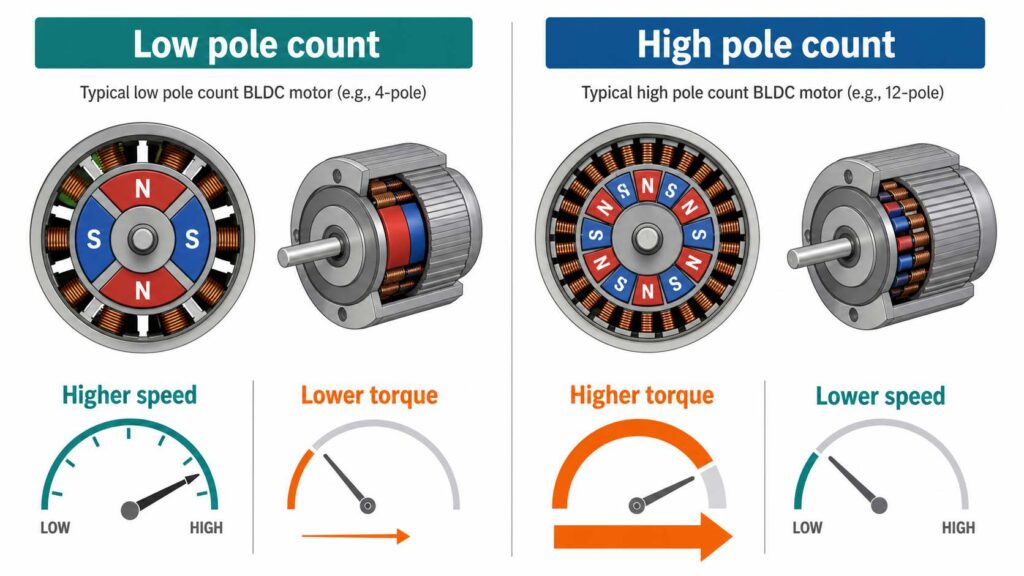
(Illustration: Comparison chart showing the typical characteristics of low-pole-count and high-pole-count BLDC motors.)
As the rotor turns, the permanent magnets rotate together with it.
However, unlike a brushed motor, no electrical current flows through the rotor itself.
Instead:
Because the rotor contains only permanent magnets and does not require electrical connections, BLDC motors eliminate the need for brushes and commutators.
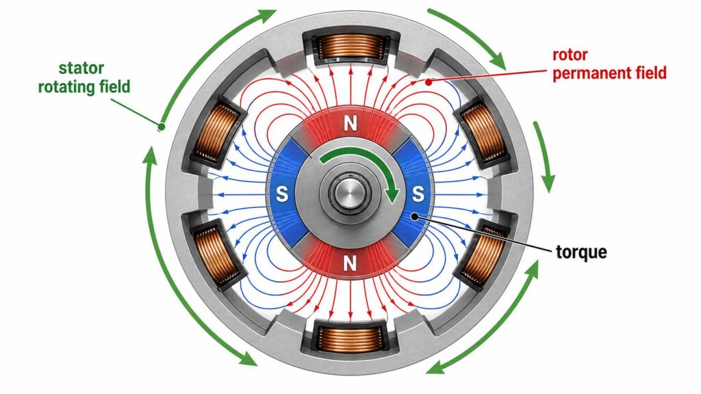
(Illustration: Diagram showing the interaction between the rotor’s permanent magnetic field and the rotating magnetic field produced by the stator.)
A small clearance exists between the rotor and the stator. This clearance is known as the air gap.
Although physically small, the air gap plays a critical role in motor performance.
An appropriately designed air gap helps:
The air gap is typically measured in fractions of a millimeter in small BLDC motors and is carefully controlled during manufacturing.
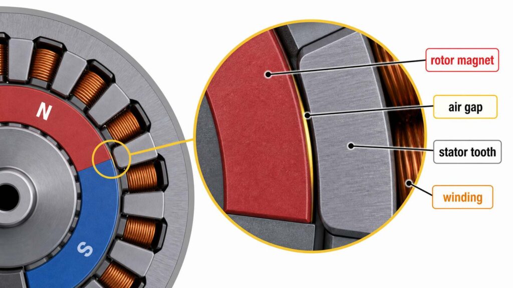
(Illustration: Enlarged cross-sectional view highlighting the air gap between the rotor magnets and stator teeth.)
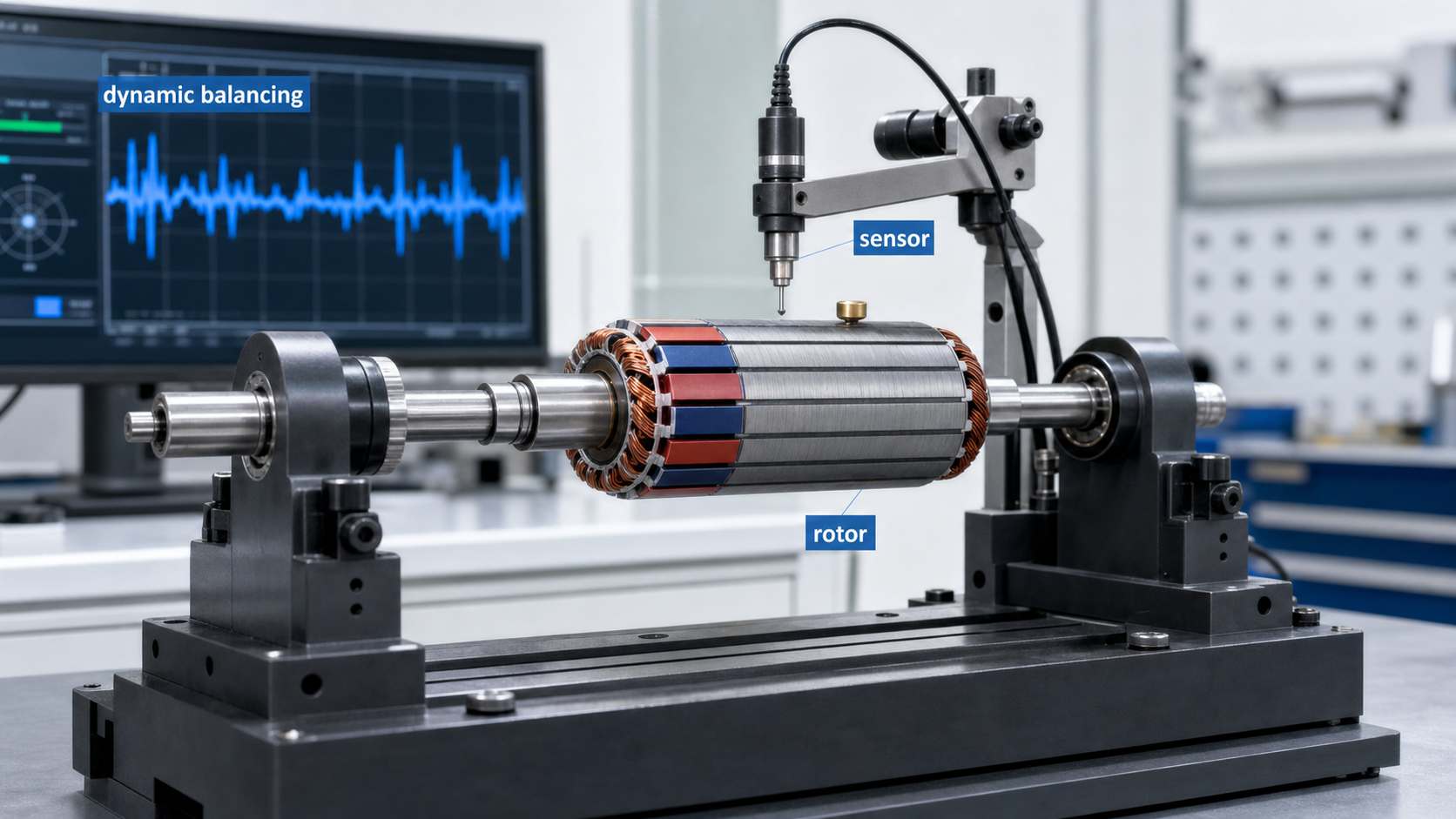
As motor speed increases, rotor balance becomes increasingly important.
Even a slight imbalance can lead to:
For this reason, high-speed BLDC rotors are dynamically balanced during manufacturing to ensure smooth and reliable operation.
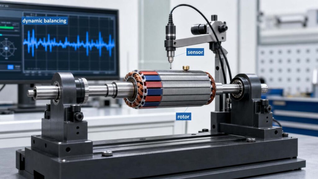
(Illustration: Rotor undergoing dynamic balancing on a balancing machine.)