Our Location
304 North Cardinal St.
Dorchester Center, MA 02124

304 North Cardinal St.
Dorchester Center, MA 02124
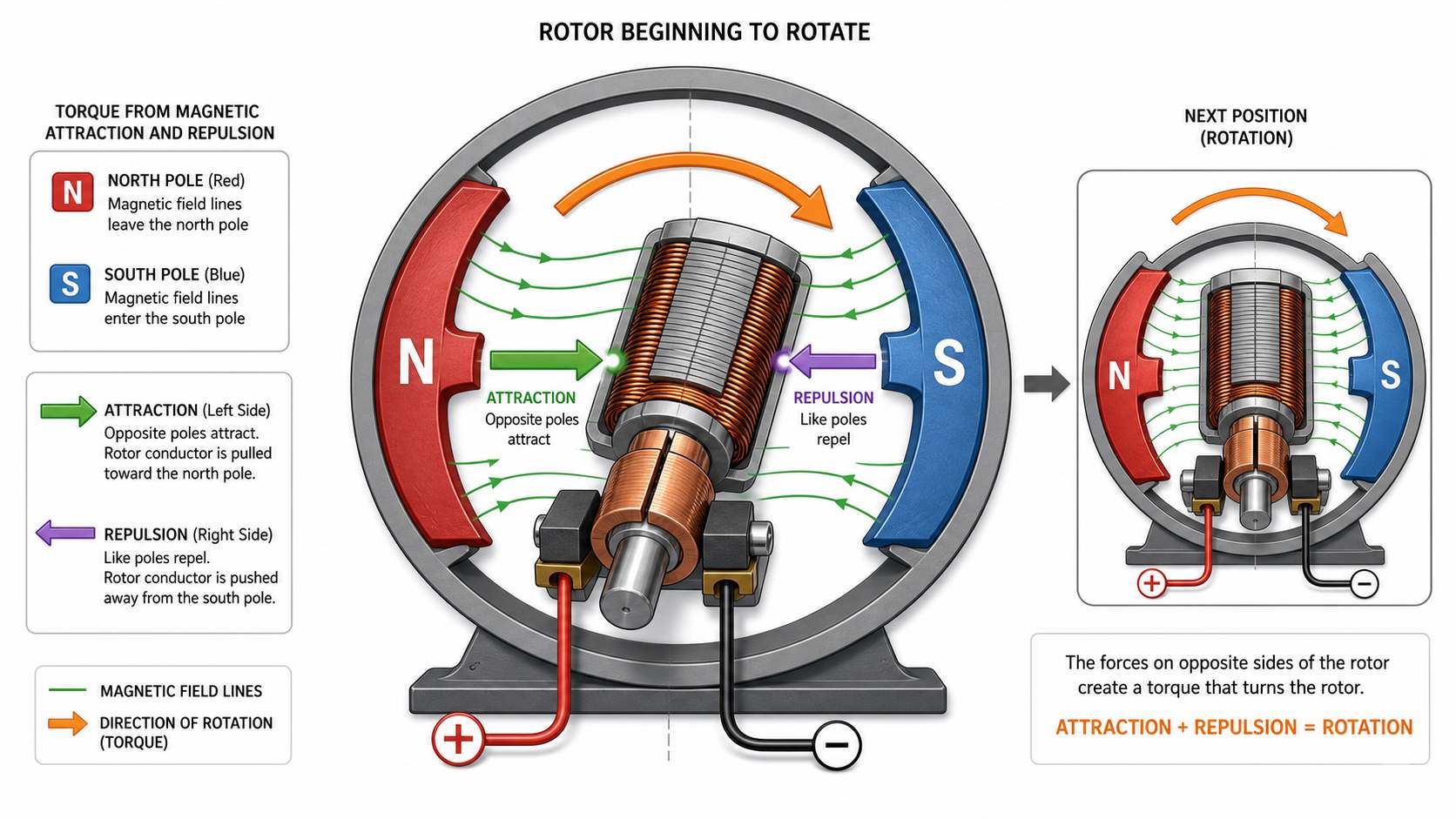
After understanding the construction of a brushed DC motor, the next step is to learn how it converts electrical energy into continuous rotational motion.
The operating principle of a brushed DC motor is based on a fundamental law of electromagnetism: a current-carrying conductor placed in a magnetic field experiences a force. By arranging conductors into coils and continuously reversing the direction of current at the correct moment, this force is transformed into continuous rotary motion.
Unlike a Brushless DC (BLDC) motor, which relies on electronic controllers for commutation, a brushed DC motor performs this switching mechanically using carbon brushes and a commutator. This simple yet effective mechanism has made brushed DC motors one of the most widely used motor types for over a century.
This chapter explains the complete operating process of a brushed DC motor, from power input to continuous shaft rotation.
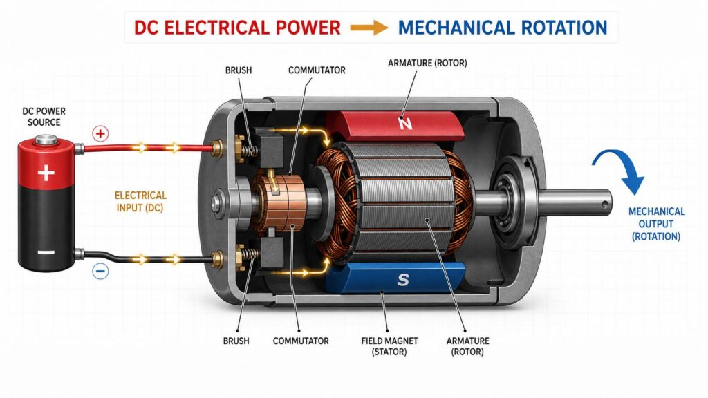
(Illustration: Overview diagram showing the energy conversion process from DC electrical power to mechanical rotation in a brushed DC motor.)
Every brushed DC motor operates by converting electrical energy into mechanical motion through the interaction between two magnetic fields.
These magnetic fields are produced by:
When these magnetic fields interact, they produce a force that causes the rotor to rotate.
This force is commonly referred to as electromagnetic torque.
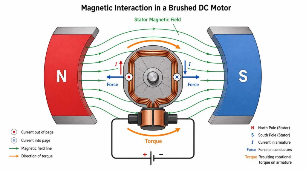
(Illustration: Simplified diagram showing the magnetic interaction between the stator field and the energized armature.)
The process begins when a DC voltage is applied to the motor terminals.
Electrical current flows through the following path:
As current flows through the armature windings, they become electromagnets.
The direction of the magnetic field depends on the direction of the current flowing through the windings.
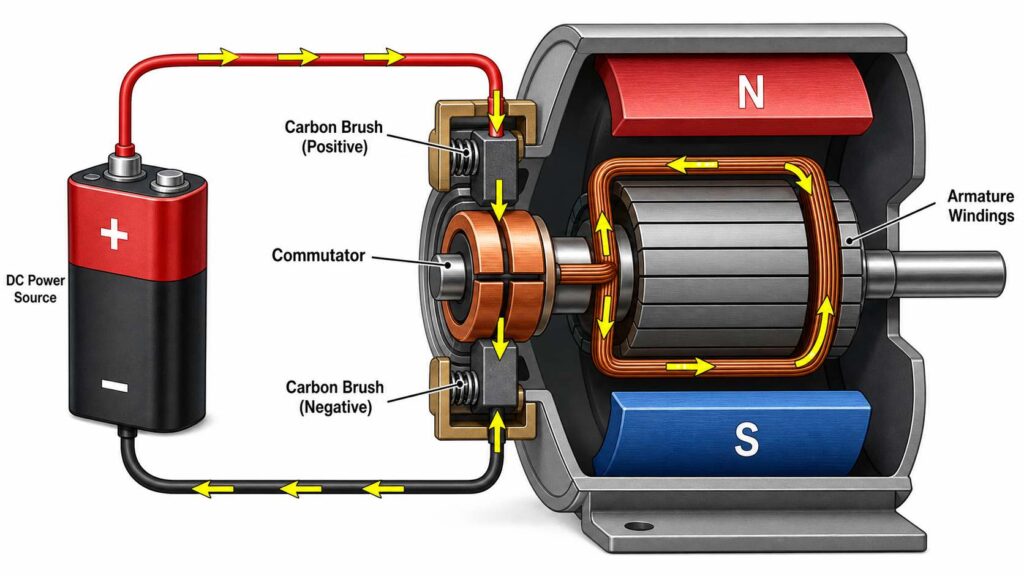
(Illustration: Current flow from the DC power source through the brushes, commutator, and armature windings.)
Once energized, the armature windings generate their own magnetic field.
The stator already provides a permanent magnetic field through either:
The interaction between these two magnetic fields creates attractive and repulsive magnetic forces.
These forces generate rotational torque.
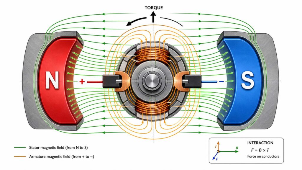
(Illustration: Magnetic field lines showing the interaction between the stator magnets and the energized armature.)
The magnetic forces acting on the armature cause the rotor to begin rotating.
Initially, the rotor moves toward a position where the opposite magnetic poles are aligned.
If nothing else occurred, the rotor would stop once magnetic equilibrium was reached.
Continuous rotation therefore requires the magnetic polarity of the armature to be reversed repeatedly as the rotor turns.
This is the purpose of the commutator.
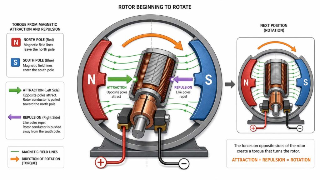
(Illustration: Rotor beginning to rotate as magnetic attraction and repulsion generate torque.)
As the rotor rotates, the commutator rotates with it.
The stationary carbon brushes remain in contact with different commutator segments.
This automatically reverses the direction of current flowing through the armature windings at precisely the correct position.
As a result:
This automatic switching process is known as mechanical commutation.
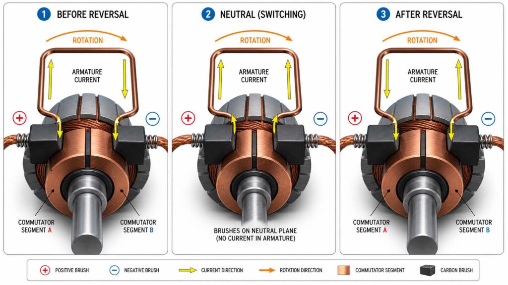
(Illustration: Sequence showing the brushes contacting different commutator segments and reversing the armature current.)
Because the commutator repeatedly reverses the current, the rotor never reaches a stable magnetic position.
Instead, it continues rotating as long as electrical power is supplied.
The operating cycle repeats continuously:
This continuous cycle converts electrical energy into smooth mechanical rotation.
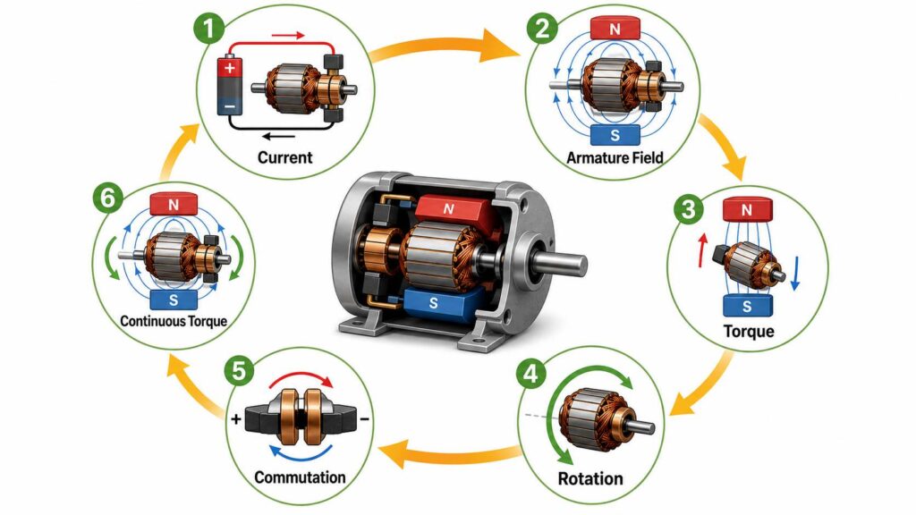
(Illustration: Circular flow diagram showing the continuous operating cycle of a brushed DC motor.)
The brushes provide the electrical connection between the stationary power supply and the rotating armature.
Without brushes:
The brushes therefore serve two essential functions:
Because they remain in physical contact with the rotating commutator, brushes gradually wear and require periodic replacement.
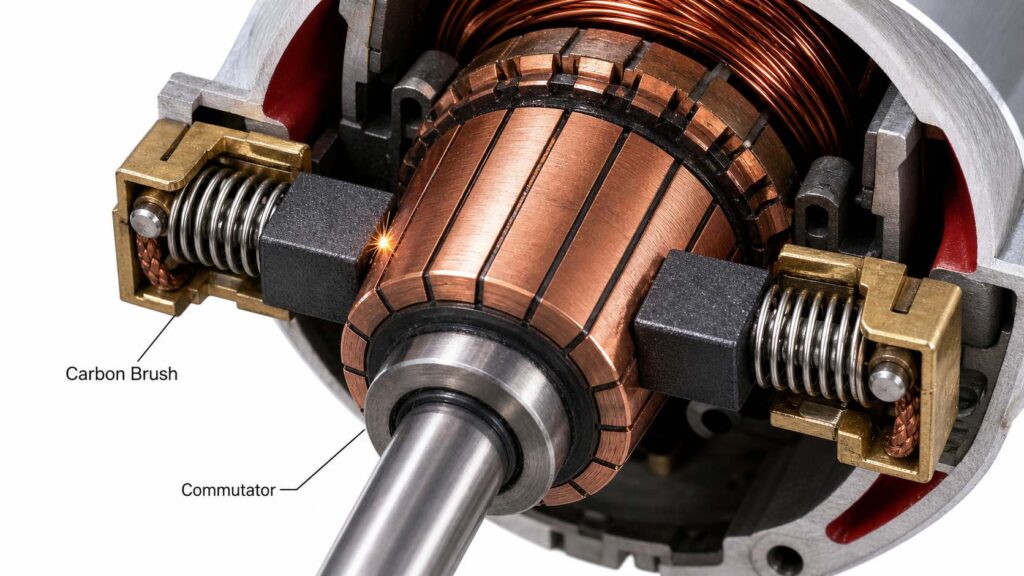
(Illustration: Close-up view of spring-loaded carbon brushes maintaining contact with the rotating commutator.)
A commutator is divided into many insulated copper segments rather than being a single continuous ring.
This segmented design allows different armature coils to be energized at different times.
Benefits include:
In general, motors with more armature coils and commutator segments operate more smoothly.
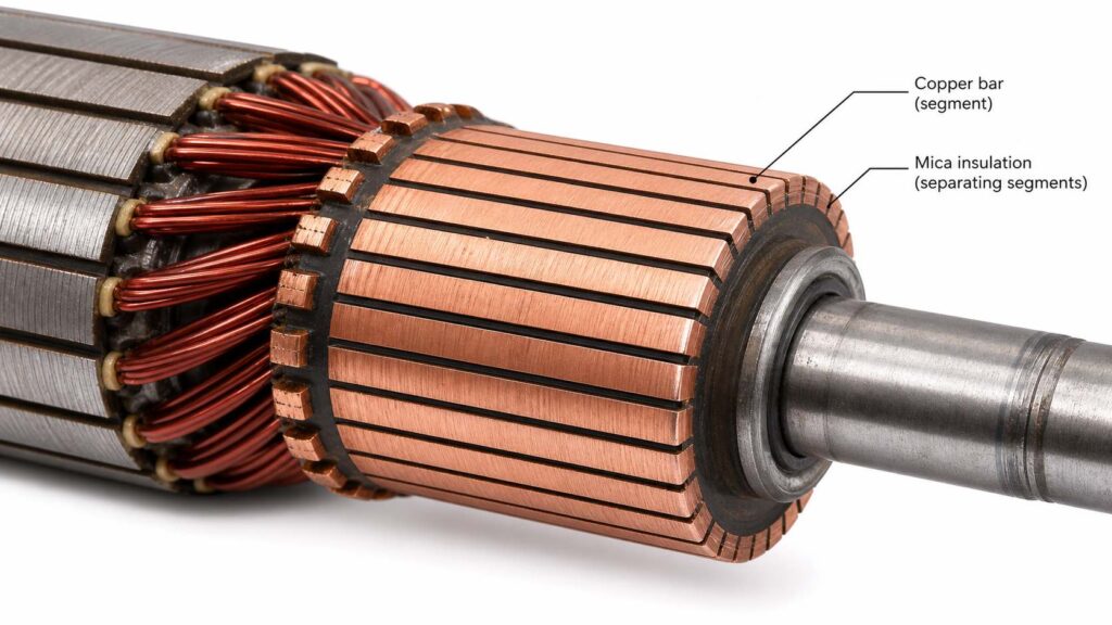
(Illustration: Enlarged view of a segmented commutator with multiple copper bars insulated from one another.)
The most important difference between brushed and brushless DC motors lies in how current is switched.
| Feature | Brushed DC Motor | Brushless DC Motor |
|---|---|---|
| Current Switching | Mechanical | Electronic |
| Switching Device | Brushes & Commutator | Motor Controller |
| Rotor Position Detection | Not required | Required (Hall sensors or sensorless control) |
| Maintenance | Higher | Lower |
| System Complexity | Lower | Higher |
Mechanical commutation makes brushed DC motors simple and inexpensive, but it also introduces friction, brush wear, electrical arcing, and maintenance requirements.
Electronic commutation eliminates these issues but requires additional control electronics.
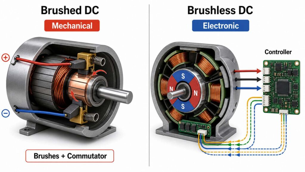
(Illustration: Side-by-side comparison of mechanical commutation and electronic commutation.)
The operation of a brushed DC motor can also be viewed as a sequence of energy transformations.
Electrical Energy
↓
Current flows through the armature windings
Magnetic Energy
↓
Magnetic fields are generated
Mechanical Energy
↓
Electromagnetic torque rotates the shaft
Some energy is inevitably lost through:
These losses explain why brushed DC motors generally have lower efficiency than brushless motors.
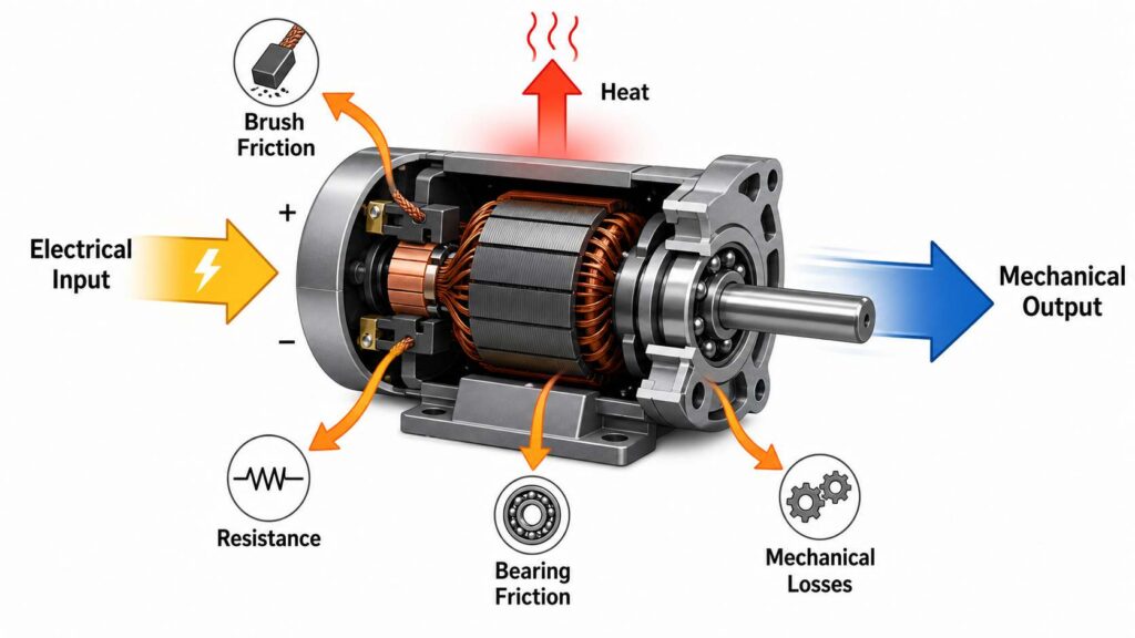
(Illustration: Energy flow diagram showing electrical input, useful mechanical output, and various energy losses.)
One common misconception is that the brushes are responsible for generating motor torque.
In reality, the brushes do not produce torque. Their primary role is to transfer electrical current to the rotating armature and enable the commutator to reverse the current at the correct time.
The actual torque is produced by the interaction between the magnetic field of the stator and the magnetic field generated by the energized armature windings.